Rockchip TC-PX30 Development Board(TC-PX30 Development Kit carrier Board )
1.TC-PX30 Development Kit Carrier Board For Stamp Hole Introduction
Rockchip TC-PX30 Development Board(TC-PX30 Development Kit carrier Board )
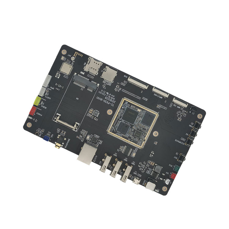
TC-PX30 development board consists of TC-PX30 stamp hole SOM and carrier board.
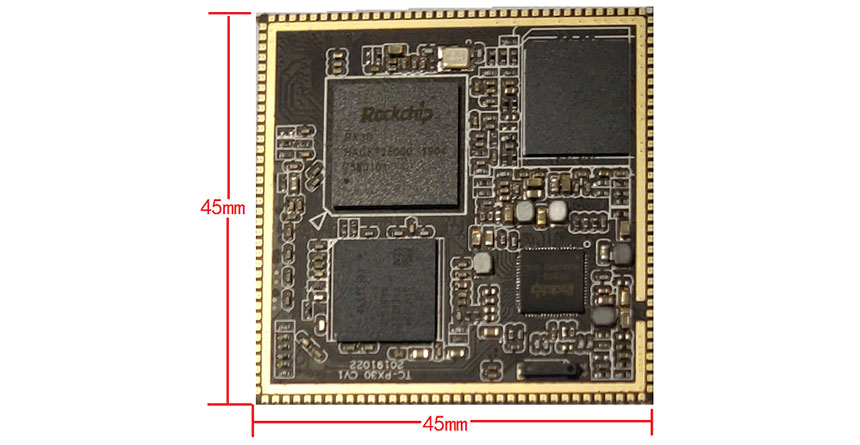
TC-PX30 system on module is based on Rockchip PX30 64 bit quad-core A35 processor. The frequency is up to 1.3GHz. Integrated with ARM Mali-G31 graphics processor, supports OpenGL ES3.2, Vulkan 1.0,OpenCL2.0, 1080p 60fts, H.264 and H.265 video decoding. It is designed with 1GB/2GB LPDDR3, 8GB/16GB/32GB eMMC,
TC-PX30 carrier board Interfaces: 4G LTE, OTG, USB2.0, 100M Ethernet, WIFI, bluetooth, audioideo input/output , G-Sensor, RGB display, LVDS/MIPI display, MIPI camera, TF card slot, extended GPIO.
It supports Android8.1, Linux and Ubuntu OS. Source code are open.
thinkcore’s open source platform core boards and development boards.thinkcore’s full suite of hardware and software customization services solutions based on Rockchip socs supports the customer’s design process, from the earliest development stages to successful mass production.
Board Design Services
Building a tailored carrier board according to customers’ requirements
Integration of our SoM in the end user’s hardware for cost reduction and lower footprint and shorten development cycle
Software Development Services
Firmware, Device Drivers, BSP, Middleware
Porting to different development environments
Integration to target platform
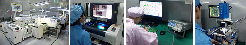
Manufacturing Services
Procurement of components
Production quantity builds
Custom labeling
Complete turn-key solutions
Embedded R & D
Technology
– Low level OS: Android and Linux, to bring up Geniatech hardware
– Driver porting: For customized hardware, building the hardware working in the OS level
– Security and authentic tool: To ensure the hardware is working in the correct way
2.TC-PX30 Development Kit Carrier Board For Stamp Hole Parameter (Specification)
|
Parameters |
|||
|
Appearance |
Stamp hole SOM + carrier board |
||
|
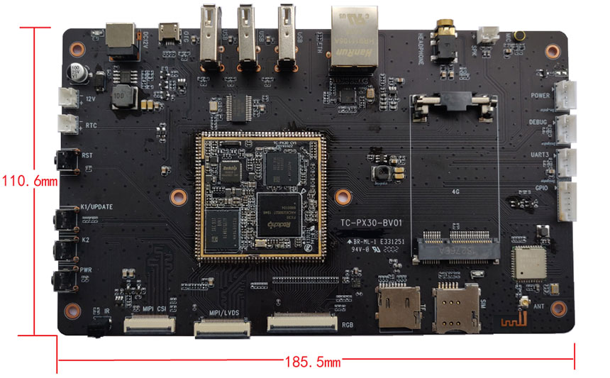
Size |
185.5mm*110.6mm |
||
|
Layer |
SOM6-layer/carrier board 4-layer |
||
|
System Configuration |
|||
|
CPU |
Rockchip PX30,Quad core A35 1.3GHz |
||
|
RAM |
Default 1GB LPDDR3, 2GB optional |
||
|
EMMC |
4GB/8GB/16GB/32GB emmc optional,default 8GB |
||
|
Power IC |
RK809 |
||
|
Interfaces parameters |
|||
|
Display |
RGB, LVDS/MIPI |
||
|
Touch |
I2C/USB |
||
|
Audio |
AC97/IIS,support record and play |
||
|
SD |
1channel SDIO |
||
|
Ethernet |
100M |
||
|
USB HOST |
3 channel HOST2.0 |
||
|
USB OTG |
1 channel OTG2.0 |
||
|
UART |
2channel uart,support flow control uart |
||
|
PWM |
1channel PWMoutput |
||
|
IIC |
4channel IICoutput |
||
|
IR |
1 |
||
|
ADC |
1 channel ADC |
||
|
Camera |
1channel MIPI CSI |
||
|
4G |
1slot |
||
|
WIFI/BT |
1 |
||
|
GPIO |
2 |
||
|
Power Input |
2 slot, 12V |
||
|
RTC Power Input |
1 slot |
||
|
Power Output |
12V/5V/3.3V |
||
|
No.# |
Signal |
No.# |
Signal |
|
1 |
GPIO0_A5 |
19 |
LCDC_VSYNC |
|
2 |
I2C1_SCL |
20 |
LCDC_DEN |
|
3 |
I2C1_SDA |
21 |
LCDC_D0 |
|
4 |
GPIO0_B4 |
22 |
LCDC_D1 |
|
5 |
PWM1 |
23 |
LCDC_D2 |
|
6 |
VCC3V3_LCD |
24 |
LCDC_D3 |
|
7 |
LVDS_TX0N |
25 |
LCDC_D4 |
|
8 |
LVDS_TX0P |
26 |
LCDC_D5 |
|
9 |
LVDS_TX1N |
27 |
LCDC_D6 |
|
10 |
LVDS_TX1P |
28 |
LCDC_D7 |
|
11 |
LVDS_CLKN |
29 |
LCDC_D8 |
|
12 |
LVDS_CLKP |
30 |
LCDC_D9 |
|
13 |
LVDS_TX2N |
31 |
LCDC_D10 |
|
14 |
LVDS_TX2P |
32 |
LCDC_D11 |
|
15 |
LVDS_TX3N |
33 |
LCDC_D12 |
|
16 |
LVDS_TX3P |
34 |
LCDC_D13 |
|
17 |
LCDC_CLK |
35 |
LCDC_D14 |
|
18 |
LCDC_HSYNC |
36 |
LCDC_D15 |
|
No.# |
Signal |
No.# |
Signal |
|
37 |
LCDC_D16 |
55 |
SDIO_CLK |
|
38 |
LCDC_D17 |
56 |
SDIO_CMD |
|
39 |
LCDC_D18 |
57 |
SDIO_D3 |
|
40 |
LCDC_D19 |
58 |
SDIO_D2 |
|
41 |
LCDC_D20 |
59 |
GPIO0_B3 |
|
42 |
LCDC_D21 |
60 |
GPIO0_B2 |
|
43 |
LCDC_D22 |
61 |
GPIO0_A1 |
|
44 |
LCDC_D23 |
62 |
GPIO2_B0 |
|
45 |
GPIO0_B5 |
63 |
GPIO0_A2 |
|
46 |
GPIO2_B4 |
64 |
I2C0_SCL_PMIC |
|
47 |
GPIO0_A0 |
65 |
I2C0_SDA_PMIC |
|
48 |
UART1_CTS |
66 |
PDM_CLK0 |
|
49 |
UART1_RXD |
67 |
I2S1_SDO |
|
50 |
UART1_TXD |
68 |
I2S1_SDI |
|
51 |
UART1_RTS |
69 |
I2S1_LRCK |
|
52 |
CLKOUT_32K |
70 |
I2S1_SCLK |
|
53 |
SDIO_D1 |
71 |
I2S1_MCLK |
|
54 |
SDIO_D0 |
72 |
GND |
|
No.# |
Signal |
No.# |
Signal |
|
73 |
MIC2_IN |
91 |
GPIO2_B6 |
|
74 |
MIC1_IN |
92 |
I2C2_SDA |
|
75 |
HP_SNS |
93 |
I2C2_SCL |
|
76 |
HPR |
94 |
MIPI_CLKO |
|
77 |
HPL |
95 |
VCC2V8_DVP |
|
78 |
SPKP_OUT |
96 |
VCC1V8_DVP |
|
79 |
SPKN_OUT |
97 |
RMII_RST |
|
80 |
GND |
98 |
RMII_CLK |
|
81 |
MIPI_CSI_D3N |
99 |
MAC_MDC |
|
82 |
MIPI_CSI_D3P |
100 |
RMII_MDIO |
|
83 |
MIPI_CSI_D2N |
101 |
RMII_RXDV |
|
84 |
MIPI_CSI_D2P |
102 |
RMII_RXER |
|
85 |
MIPI_CSI_CLKN |
103 |
RMII_RXD1 |
|
86 |
MIPI_CSI_CLKP |
104 |
RMII_RXD0 |
|
87 |
MIPI_CSI_D1P |
105 |
RMII_TXD0 |
|
88 |
MIPI_CSI_D1N |
106 |
RMII_TXD1 |
|
89 |
MIPI_CSI_D0P |
107 |
RMII_TXEN |
|
90 |
MIPI_CSI_D0N |
108 |
GND |
|
No.# |
Signal |
No.# |
Signal |
|
109 |
VCC5V0_SYS |
127 |
FLASH_WRN |
|
110 |
VCC5V0_SYS |
128 |
FLASH_CS1 |
|
111 |
GND |
129 |
FLASH_RDN |
|
112 |
GND |
130 |
SDMMC0_D2 |
|
113 |
EXT_EN |
131 |
SDMMC0_D3 |
|
114 |
VCC5V0_HOST |
132 |
SDMMC0_CMD |
|
115 |
VCC_RTC |
133 |
VCC_SD |
|
116 |
VCC3V3_SYS |
134 |
SDMMC0_CLK |
|
117 |
VCC3V0_PMU |
135 |
SDMMC0_D0 |
|
118 |
VCC_1V8 |
136 |
SDMMC0_D1 |
|
119 |
OTG_DP |
137 |
SDMMC0_DET |
|
120 |
OTG_DM |
138 |
RESET_KEY |
|
121 |
USB_ID |
139 |
POWER_KEY |
|
122 |
USB_DET |
140 |
ADC0 |
|
123 |
USB_HOST_DM |
141 |
ADC1 |
|
124 |
USB_HOST_DP |
142 |
ADC2 |
|
125 |
FLASH_CS0 |
143 |
IR_IN / PWM3 |
|
126 |
FLASH_CLE |
144 |
GPIO0_B7 |
|
Interfaces details |
||
|
NO.# |
Name |
Description |
|
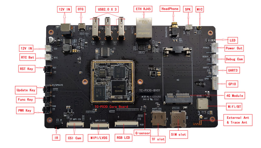
【1】 |
12V IN |
12V Power input |
|
【2】 |
RTC Bat |
RTC Power input |
|
【3】 |
RST Key |
Reset key |
|
【4】 |
Update Key |
Update key |
|
【5】 |
Func Key |
Function key |
|
【6】 |
PWR Key |
Power key |
|
【7】 |
IR |
IR receive |
|
【8】 |
CSI Cam |
MIPI CSI camera |
|
【9】 |
MIPI/LVDS |
MIPI/LVDS display |
|
【10】 |
RGB LCD |
RGB display |
|
【11】 |
G-sensor |
G-sensor |
|
【12】 |
TF slot |
TF card slot |
|
【13】 |
SIM slot |
4G SIM Card slot |
|
【14】 |
Exteral & Trace Ant |
Wifi/BT antenna, including onboard and socket |
|
【15】 |
WIFI/BT |
WIFI/BT module AP6212 |
|
【16】 |
4G Module |
PCIE 4G module slot |
|
【17】 |
GPIO |
GPIO expansion |
|
【18】 |
UART3 |
Uart3,ttl level |
|
【19】 |
Debug Com |
Debug UART |
|
【20】 |
Power Out |
Power output |
|
【21】 |
LED |
LED control by GPIO |
|
【22】 |
MIC |
Audio input |
|
【23】 |
SPK |
speaker output |
|
【24】 |
HeadPhone |
Audio earphone output |
|
【25】 |
ETH RJ45 |
100M Ethernet RJ45 |
|
【26】 |
USB2.0 X 3 |
3*USB2.0 HOST TypeA |
|
【27】 |
OTG |
OTG mini USB |
|
【28】 |
TC-PX30 Core Board |
TC-PX30 SOM |